QA探针
QA Technology Company’s philosophy embraces the concepts of Total Customer Satisfaction, Continual Improvement, and Teamwork as the vehicles for achieving our goals of providing the best products and services to our Customers. Our registration to ISO 9001:2008 demonstrates our commitment to Quality and the effectiveness of our Quality System. Although our Quality Assurance efforts encompass all aspects of our operations, the strict and comprehensive monitoring of our processes and products is the cornerstone of our Quality System and is an attribute which distinguishes us from our competition.
In order to ensure QA has the best products and the capability to provide technical support to Customers on application problems, it is critical that we have state of the art test facilities. Our computer controlled probe life cycle testers, extensive metalographic lab, and Scanning Electron Microscope are examples of the equipment in place to support our product testing/failure analysis activities.


Conventional Probe & Socket Design …………………………………………. 6
.025 inch Centers
.160 Stroke – 025-16 Series……………………………………………. 14
.039 inch Centers
.160 Stroke – 039-16 Series……………………………………………. 16
.250 Stroke – 039-25 Series……………………………………………. 18
.050 inch Centers
.050 Stroke – 050-05 Series……………………………………………. 20
.160 Stroke – 050-16 Series……………………………………………. 22
.250 Stroke – 050-T25 Series ………………………………………….. 24
.250 Stroke – 050-R25 Series………………………………………….. 26
.400 Stroke – 050-T40 Series ………………………………………….. 28
.075 inch Centers
.250 Stroke – 075-25 Series……………………………………………. 30
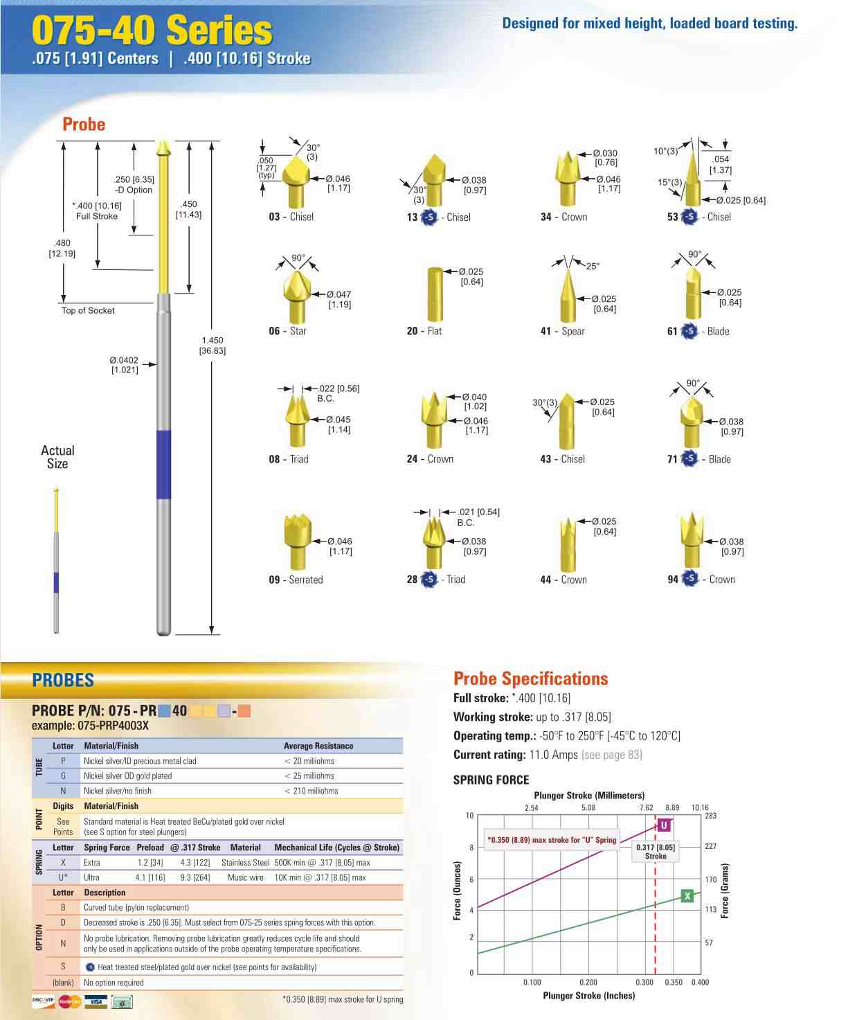
.400 Stroke – 075-40 Series……………………………………………. 32
.100 inch Centers
.050 Stroke – 100-05 Series……………………………………………. 34
.160 Stroke – 100-16 Series……………………………………………. 36
.250 Stroke – 100-25 Series……………………………………………. 38
.400 Stroke – 100-40 Series……………………………………………. 40
.125 inch Centers
.250 Stroke – 125-25 Series……………………………………………. 42
Double-Ended Sockets……………………………………………………… 44
Interface Probes………………………………………………………………………..46
X Probe ? Socketless Series
.031 inch Centers
.250 Stroke – X31-25 Series……………………………………………. 48
.039 inch Centers
.250 Stroke – X39-25 Series……………………………………………. 50
.400 Stroke – X39-40 Series……………………………………………. 52
.050 inch Centers
.250 Stroke – X50-25 Series……………………………………………. 54
.400 Stroke – X50-40 Series……………………………………………. 56
.075 inch Centers
.250 Stroke – X75-25 Series……………………………………………. 58
.400 Stroke – X75-40 Series……………………………………………. 60
Double-Ended Terminations………………………………………………. 62
Ball Grid Array (BGA) Probes
.8mm Centers
M08–PRH89 Series ……………………………………………………….. 64
Tools ………………………………………………………………………………………… 66
Selection
Spring Force Considerations………………………………………………….. 68
Probe Tubes Finish Options……………………………………………………. 69
No-Clean Flux Applications……………………………………………………. 70
Organic Solderability Preservatives (OSP) Selection ………………….. 70
PROBES & SOCKETS (CONT.)
Lead-Free Solder PCB Processes……………………………………………. 70
Solving Today’s Test Challenges – Steel Razor …………………………. 72
High Pre-load Spring Option for PB-Free, OSP and No-Clean…………74
How Probe Tip Geometry Affects Contact Reliability …………………. 74
Plunger Materials–Beryllium Copper vs. Steel Plungers……………… 76
Long Stroke Probes for Dual-level Testing………………………………… 76
Decreased Stroke Probes ……………………………………………………… 77
Probing Solder Bump/Dome Targets…………………………………………78
Lubricated vs. Unlubricated Probes…………………………………………. 79
Working Temperature Ranges………………………………………………… 79
Common Failure Modes for Test Probes…………………………………… 80
Socket Selections………………………………………………………………… 81
Performance
Socket Push Out Force …………………………………………………………. 82
Current Carrying Capacity……………………………………………………… 83
Pointing Accuracy………………………………………………………………… 87
Wireless Probing and High Frequency Performance…………………… 90
Probe Maintenance ……………………………………………………………… 92
Instructions
Socket Set Heights………………………………………………………………. 94
Socket and Probe Installation Instructions……………………………….. 95
Tool Tip Replacement Instructions……………………………………………95
Probe Removal Instructions…………………………………………………… 96
Socket Removal Instructions…………………………………………………. 96
025-16 Series Installation Notes ……………………………………………. 97
Wire Plug Installation Instructions ………………………………………….. 99
Wire Jack Installation Instructions………………………………………….. 99
Wire Jack Crimper Operating Procedure………………………………… 100
Wire Grip Installation Instructions…………………………………………..100
Wire Grip Removal Instructions……………………………………………..100
Wire Wrapping 50-mil Centers…………………………………………….. 100
Indicator Probes…………………………………………………………………. 102
Solder Connections on Soldered Sockets………………………………. 102
Socket Plugs……………………………………………………………………….102
Double-Ended Sockets for Wireless Fixturing …………………………. 103
SOCKETLESS TECHNOLOGY – X PROBE ?
X Probe ? Socketless Technology
X Probe Socketless Technology ……………………………………………. 104
Advantages and Features …………………………………………………… 104
Termination Selection…………………………………………………………..105
Fixture Platform…………………………………………………………………. 106
Engineering Change Orders …………………………………………………. 109
Drilling Suggestions……………………………………………………………. 109
Calculating Termination Set Heights……………………………………… 111
Termination Installation Instructions ……………………………………… 112
Probe Installation……………………………………………………………….. 112
Benefits of the Spacer Plate………………………………………………… 113
Termination Removal Instructions ………………………………………… 114
Removal Techniques for Damaged X Probes…………………………… 115
Reinstalling the Termination…………………………………………………. 116
Current Carrying Capacity……………………………………………………. 116
FREQUENTLY ASKED QUESTIONS
Conventional Product FAQs………………………………………………….. 119
X Probe Product FAQs…………………………………………………………. 121
X Probe Fixturing FAQs……………………………………………………….. 122
100-PRP 2541H-S 100-PRP 2520H-S 100-PRP 2522H-S
100-PRP 2504H-S 100-PRP 2540H-S 100-PRP 2529H-S
100-PRP 2503H-S 100-PRP 2501H-S 100-PRP 2531H-S
100-PRP 2584H-S 100-PRP 2508H-S 100-PRP 2507H-S
100-PRP 2531H-S 100-PRP 2524H-S 100-PRP 258RH-S
100-PRP 2543H-S 100-PRP 2507H-S 100-PRP 2508H-S
100-PRP 2563H-S 100-PRP 2543H-S 100-PRP 256RH-S
100-PRP2589H-S 100-PRP2584H-S 100-PLP1670L
075-PRP2509L 100-PRP2553X-S 100-PRP2561X-S
075-PRG2524H 075-PRP2561X-S 050-PLP1603H
100-PRP4003H-S 100-PRP4009X
